
(Centralized External Connectivity — Guided Edge Deployment wizard)
All preparatory work described in earlier articles has already been completed:
— VCF 9 is operational with the full management stack.
— pfSense acts as the ToR router and provides external connectivity.
— VLANs for management, TEP, and BGP uplinks are in place.
— The entire data path (VDS / pfSense) is set to MTU ≥ 1700.
— All required TCP/UDP ports for NSX are open.The final step before enabling VCF Automation is to deploy an NSX Edge cluster and a Tier-0 gateway in Active-Standby mode.
0 Prerequisites
| Component | Example value |
|---|---|
| VLAN-TEP (hosts & Edge) | 40 |
| Uplink VLAN A / B | 80 / 81 |
| Uplink subnet A / B | 172.16.80.0/24 / 172.16.81.0/24 |
| pfSense ASN | 65000 |
| NSX Edge ASN | 65001 |
Important The ESXi cluster must use a vSphere Distributed Switch (VDS) that has already been added to NSX as a transport node; otherwise the wizard will not offer Use host overlay network configuration and you will have to define Edge TEPs manually.
1 Launching the wizard
- In vCenter, navigate to Networking ▶ Network Connectivity ▶ Configure Network Connectivity — the start screen.

2. Select Centralized Connectivity and click Next

1.1 “Networking Prerequisites” checklist

The checklist appears every time; you must tick every item before the Continue button becomes active.
2 Edge Cluster
- Edge Cluster Name
vcf-edge-cl - Tunnel Endpoint MTU 1700
- Edge Form Factor Small (lab) or Large (production)

2.1 First Edge node
| Field | Value |
|---|---|
| FQDN | vcf-edge-01.vcf.lab |
| Cluster / RP / Datastore | vworld-cl01 / Resources / vsan01 |
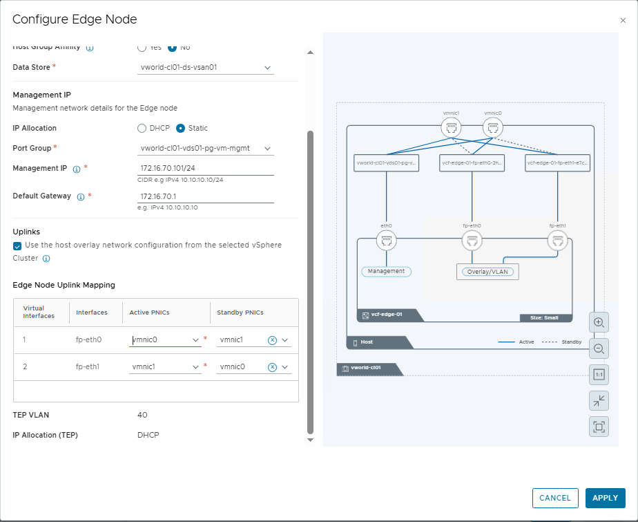
| Management IP | 172.16.70.101/24 |
| Management Gateway | 172.16.70.1 |
| Mgmt Port Group | vworld-cl01-vds01-pg-vm-mgmt |
Tick Use host overlay network configuration — the wizard inherits the TEP VLAN, IP pool, and teaming policy from the transport nodes.
Uplink mapping: fp-eth0 → vmnic0, fp-eth1 → vmnic1

2.2 Second Edge node (clone)
| Field | Value |
|---|---|
| Edge Node Name | vcf-edge-02.vcf.lab |
| Management IP | 172.16.70.102/24 |
Save the clone

Both nodes appear in the table.

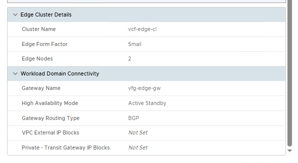
3 Workload Domain Connectivity (Tier-0 gateway)
| Field | Value |
|---|---|
| Gateway Name | vcf-edge-gw |
| High Availability Mode | Active Standby |
| Gateway Routing Type | BGP |
| Local ASN | 65001 |
Why Active-Standby HA is mandatory
NSX Edge maintains stateful services (NAT, DHCP, VPN). In Active-Standby mode:
- Session tables are replicated to the standby node, so vMotion and upgrades occur without traffic loss.
- VCF Lifecycle Manager safely toggles Active ↔ Standby during lifecycle tasks.
- L4-7 services used by VCF Automation meet the high-availability requirements for tenant VPCs.
3.1 Configuring BGP uplinks
| Edge node | VLAN | Edge IP | pfSense IP | Edge ASN | pfSense ASN |
|---|---|---|---|---|---|
| vcf-edge-01 | 80 | 172.16.80.2/24 | 172.16.80.1 | 65001 | 65000 |
| vcf-edge-01 | 81 | 172.16.81.2/24 | 172.16.81.1 | 65001 | 65000 |
| vcf-edge-02 | 80 | 172.16.80.3/24 | 172.16.80.1 | 65001 | 65000 |
| vcf-edge-02 | 81 | 172.16.81.3/24 | 172.16.81.1 | 65001 | 65000 |
For each node click Set

,

. After saving, the Gateway Uplinks column shows “2”

4 Review & Deploy
Verify:
- The topology diagram

- The parameter summary
Click Deploy. The system:
- Creates the Edge cluster (two VMs).
- Configures TEP and BGP uplinks.
- Deploys the Tier-0 gateway in Active-Standby mode and links it to a Transit Gateway.

5 Validation and IP block preparation
- NSX Manager ▶ Tier-0 Gateways —
vcf-edge-gwshows status Success

- Networking ▶ IP Address Pools ▶ IP Address Blocks — create at least:
- One External block (e.g.
10.250.0.0/24), - And, if required, a Private block for the Transit Gateway.
The steps are illustrated in
- One External block (e.g.


These blocks are mandatory for VCF Automation to allocate NAT addresses and VPC subnets.
6 Proceeding to VCF Automation
With the Edge cluster, Tier-0 gateway, and IP blocks in place, launch the VCF Automation wizard.