Introduction
Can we take a running virtual machine from a classic NSX segment, hand it over to vSphere Supervisor and VM Service, and do it without changing its IP address or shutting it down?
That was the question I wanted to answer in my VCF 9.1 lab.
The answer is yes, but it is not a single wizard. Getting from “a VM on an old Tier-1 segment” to “a VM Operator object in a Namespace, routed through a VPC and Transit Gateway” requires careful work on the provider side, the tenant side, the NSX Edge, and the Mobility Operator.
In this article, we will build the whole procedure step by step. We will prepare an External IP Block and a Public VPC subnet with exactly the same CIDR as the source segment, temporarily stretch L2 with an NSX Edge Bridge, import the VM with Mobility Operator in preserve mode, and finally move L3 routing from the source Tier-1 to the Transit Gateway in a controlled cutover.
This is written as a validated, click-by-click proof of concept. I will show not only what to configure, but also why each step matters and what to verify before moving on.
What makes this lab interesting?
The VM keeps its IP, its MAC, its default gateway and its uptime. During the whole migration a continuous ping is running, and the only visible interruption is a short gap during the routing cutover.
The Lab Configuration
Before copying values from the steps below, here is the complete working configuration, so that the names used later make sense.
| Component | Working lab value |
|---|---|
| Platform | VCF 9.1.x / NSX / VCF Automation / vSphere Supervisor |
| Source Tier-1 | vworld-t1-gw01 |
| Tier-0 | vworld-t0-gw01 |
| Source segment | vcf-migration-test-public |
| Migration CIDR | 192.168.107.0/24 |
| Default gateway | 192.168.107.1 |
| VM | test-0006 / vm-4039 |
| VM IP / MAC | 192.168.107.20 / 00:50:56:9c:6e:cc |
| Organization / NSX Project | test-org-auto / a85bcc0c-ad2f-45bb-9593-b7640713f0dc |
| Transit Gateway | migration-poc-tgw |
| Connectivity Profile | migration-poc-tgw-cp-5gn8 |
| External Connection | test-centralized-connection |
| External IP Block | migration-poc-public-107-block (192.168.107.0/24) |
| Target VPC | vpc-migration-poc-public-107 |
| Target subnet | subnet-c5mk (Public, 192.168.107.0/24) |
| Namespace | migration-poc-public-107-ns-2c7tm |
| Edge cluster/nodes | vworld-edge-cl01 / vcf-edge-01, vcf-edge-02 |
| Bridge Profile | migration-poc-bridge-profile |
| Bridge VLAN TZ | migration-bridge-vlan-tz |
| Parent segment | migration-parent-seg |
| Bridge VLAN | 102 |
Do not treat these values as universal.
These are the names and addresses from my lab. What is reusable is the architecture, the order of operations and the dependency chain.
Prerequisites
I assume that the basic platform already exists. Before we begin, verify that you have:
- a healthy VCF 9.1 deployment with VCF Automation,
- a vSphere Supervisor enabled with NSX VPC networking,
- an operational NSX Edge Cluster and Provider Tier-0,
- a Centralized External Connection and a Transit Gateway used by the organization,
- Mobility Operator available in the Supervisor,
- an external host from which you can run a continuous ping to the VM.
If all of those are in place, we can start.
Part 1 – Understand the Design Before Opening Any Wizard
If this is your first migration of this kind, it helps to understand the moving parts first. The procedure has four phases:
- Prepare the target – a Public VPC subnet with exactly the same CIDR as the source segment, with VPC Gateway Connectivity switched off.
- Stretch L2 – an NSX Edge Bridge connects the target subnet and the source segment into one broadcast domain.
- Import the VM – Mobility Operator changes the network backing and hands the VM over to VM Service in
preservemode. - Move L3 – routing for the prefix is transferred from the source Tier-1 to the Transit Gateway and the External Connection.
The VCF Automation objects involved form a clear hierarchy:
VCF Automation Organization (test-org-auto)
 |
 v
Project (default-project / NSX Project UUID)
 |
 v
Namespace (VM Service boundary)
 |
 v
Dedicated VPC  <-- VPC Subnet (Private / Private_TGW / Public / L2_Only)
 |                       ^
 v                       |
Connectivity Profile --- IP Blocks (External / Private-VPC / Private-TGW)
 |
 v
Transit Gateway
 |
 v
External Connection (provider / Tier-0 side)
Public does not mean “Internet” here.
In this design, Public is the address-scope classification of a subnet backed by an External IP Block. That is what allows the existing Centralized External Connection to advertise the prefix towards Tier-0 as a TGW route.
The components you will touch
| Component | Role in the migration |
|---|---|
| Source Tier-1 | Owns gateway 192.168.107.1/24 before migration. During cutover we suppress only the migrated prefix. |
| Tier-0 | Our routing observation point: the prefix is t1c before cutover and tgws after. |
| Centralized External Connection | Northbound path from the TGW to Tier-0. It advertises External IP Blocks, so allow_private is not needed. |
| Transit Gateway | Connects the VPC to the External Connection. The Public subnet enters TGW routing once Gateway Connectivity is on. |
| Connectivity Profile | Ties Region, TGW and IP blocks together. Without the block here, the tenant cannot select it for a Public subnet. |
| External IP Block | Makes 192.168.107.0/24 a valid source for a Public subnet. |
| Public VPC subnet | Target network with the same CIDR; Gateway Connectivity stays off until cutover. |
| Namespace | Must share the subnet so it appears as a Subnet CR for the Mobility Operator. |
| Bridge Profile, VLAN TZ, parent segment | Shared bridge infrastructure on the Edge; each migrated L2 domain gets a unique VLAN tag. |
| Mobility Operator | ImportOperationBatch / ImportOperation: precheck, network backing change, relocation and commit. |
How the traffic flows
This is the most important picture in the whole article:
BEFORE
VM 192.168.107.20 -> Source Segment -> T1 192.168.107.1 -> T0 -> upstream

DURING IMPORT
VM -> Target SubnetPort -> L2 Bridge (VLAN 102) -> Source Segment -> Source T1 gateway

AFTER CUTOVER
VM -> Public VPC Subnet -> TGW -> Centralized External Connection -> T0 -> upstream
The target subnet exists from the very beginning, but its gateway is disabled. This prevents two active gateways for the same IP.
The golden rule of this procedure
Build the bridge before the import and remove it only after the L3 cutover has been validated. During the import, the source Tier-1 still owns the gateway and routing.
Part 2 – Provider-Side Preparation
Step 1 – Check the Centralized External Connection
- Open Provider Management > Networking > External Connections / Centralized Connections.
- Select the connection the organization uses. In my lab, it was
test-centralized-connection. - Verify that it is healthy and connected to the Transit Gateway
migration-poc-tgw.
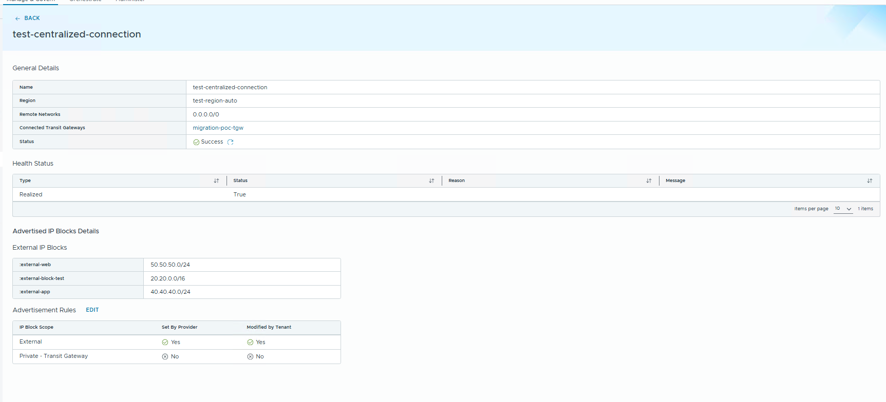
Figure 1. The Centralized External Connection used by migration-poc-tgw.
Do not enable Advertise Private TGW.
The working design uses an External IP Block and a Public subnet. As you will see in the “What did not work” section, the Private-TGW path was blocked in my lab anyway.
Step 2 – Create an External IP Block for the Migrated Prefix
- Open Provider Management > Networking > External IP Blocks.
- Click NEW.
- Name: a unique name, for example
migration-poc-public-107-block. - Region: the organization region.
- CIDR: the exact source prefix,
192.168.107.0/24. - Save.
Checkpoint: the block must show Status = Normal.
Step 3 – Associate the Block with the Centralized External Connection
- Open Provider Management > Networking > Centralized Connections.
- Open the connection the organization uses.
- Open IP Blocks.
- Under Associated External IP Blocks, click NEW.
- Select the new block and save.
Checkpoint: The block shows Status = Normal on the connection.
Step 4 – Assign the Block to the Organization
- Open Provider Management > Organizations and select the organization.
- Go to Networking > External IP Block.
- Assign the new block.
- Set the IP and CIDR quota. My lab needed exactly one
/24CIDR. - If the tenant does not see the change, click SYNC on the organization Networking page.
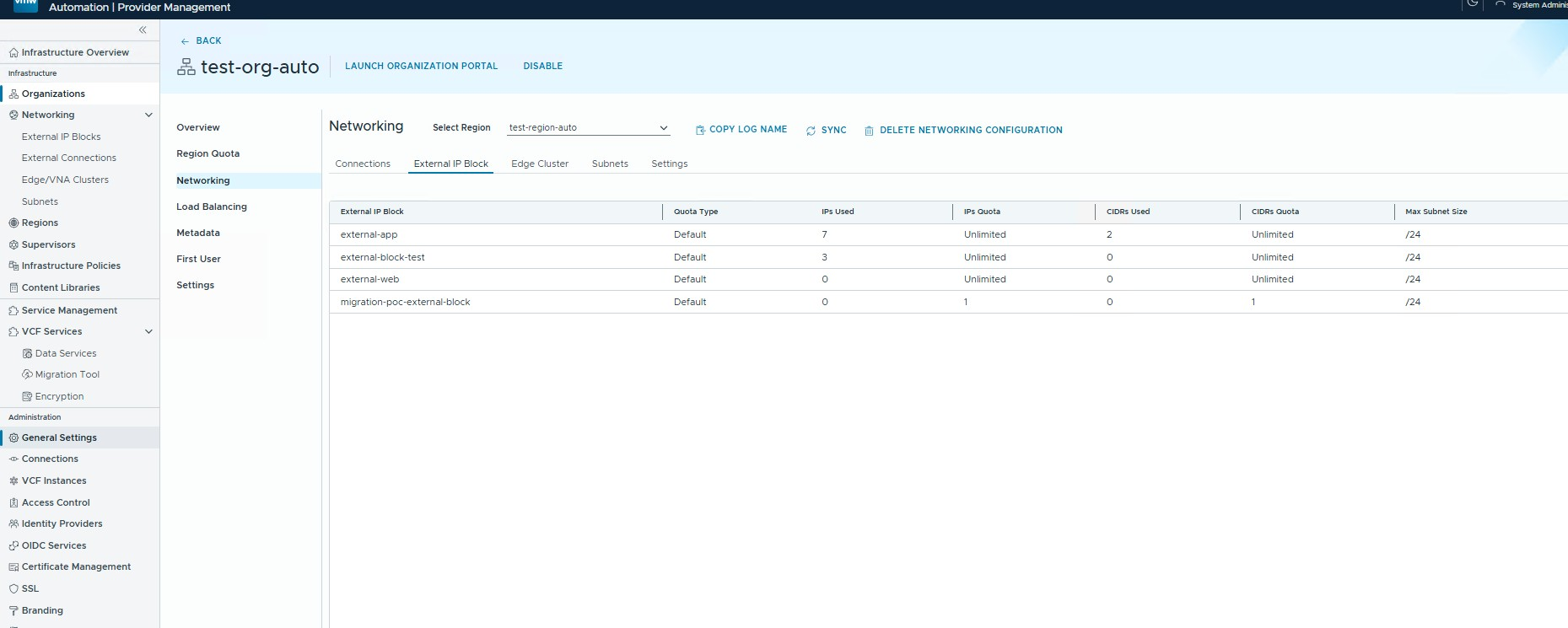
Figure 2. The External IP Block assigned to the organization with enough quota for the /24.
Step 5 – Add the Block to the Connectivity Profile
This is one of the easiest steps to miss. The External Connection association and the organization quota are not enough. The Connectivity Profile must also list the block under External IPv4 blocks.
- As Tenant / Service Administrator, open Manage & Govern > Networking > Connectivity Profiles.
- Edit
migration-poc-tgw-cp-5gn8. - Transit gateway:
migration-poc-tgw. - External IPv4 blocks: add
migration-poc-public-107-block. - Private – TGW IPv4 blocks: leave unchanged.
- Save.
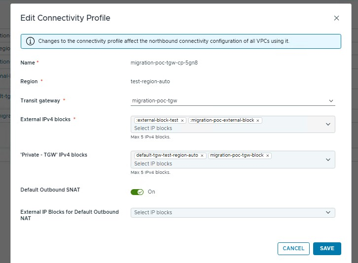
Figure 3. Connectivity Profile with the External IPv4 blocks. The screenshot comes from an earlier 192.168.106.0/24 test; in production, select the actual migrated block.
Why is this step critical?
If the block is not in the Connectivity Profile, it simply will not appear in the IP Block list when the tenant creates a Public subnet. Everything else looks correct, which makes this mistake hard to spot.
Part 3 – Build the Target VPC, Public Subnet and Namespace
Step 6 – Create the VPC
- Open Manage & Govern > VPCs > NEW VPC.
- Use the following values:
| Field | Value |
|---|---|
| Name | vpc-migration-poc-public-107 |
| Region | The same region as the Connectivity Profile |
| Connectivity profile | migration-poc-tgw-cp-5gn8 |
| Private – VPC IPv4 CIDRs | Empty for this POC |
- Click CREATE and wait for Success.
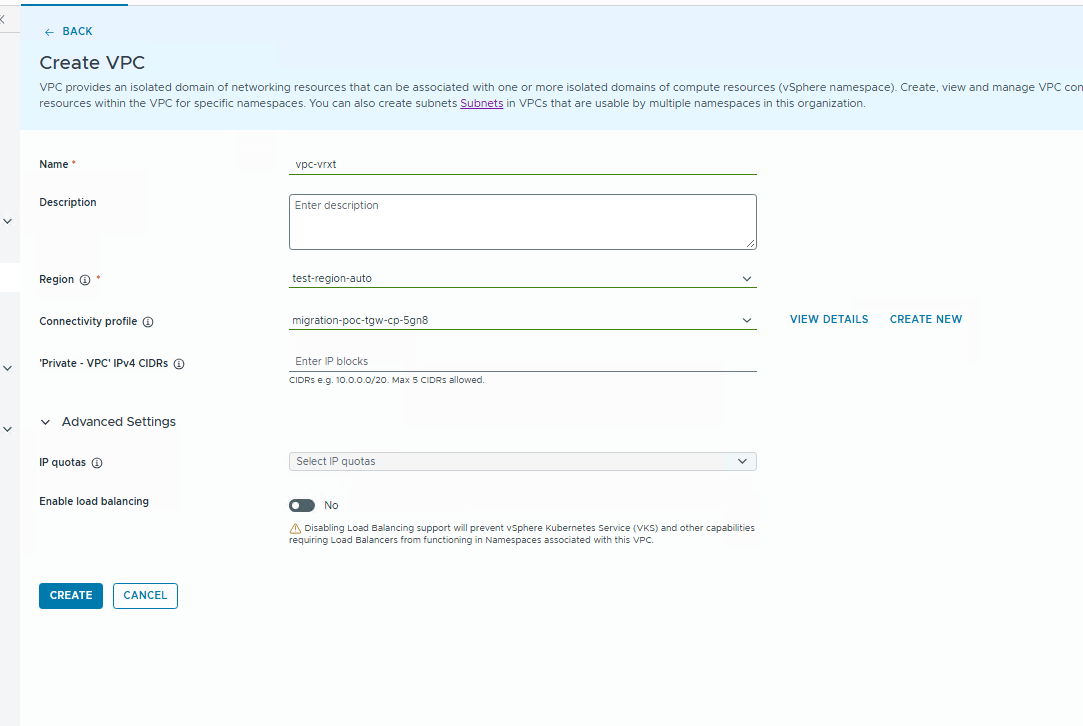
Figure 4. Create VPC.
Note that Public is not a VPC mode. You choose Public later, on the subnet.
Step 7 – Create the Public Subnet with Gateway Connectivity Off
- Open Manage & Govern > Subnets > NEW SUBNET.
- Configure:
| Field | Value |
|---|---|
| Region | test-region-auto |
| VPC | vpc-migration-poc-public-107 |
| Access Mode | Public |
| IP Block | migration-poc-public-107-block (do not use Any in production) |
| Auto-allocate from IP Block | Off, because we need the exact prefix |
| IP Address CIDR | 192.168.107.0/24 |
| VPC Gateway Connectivity | No / Off |
| Static IP Allocation | Yes |
| DHCP | None |
- Click CREATE and wait for Success.
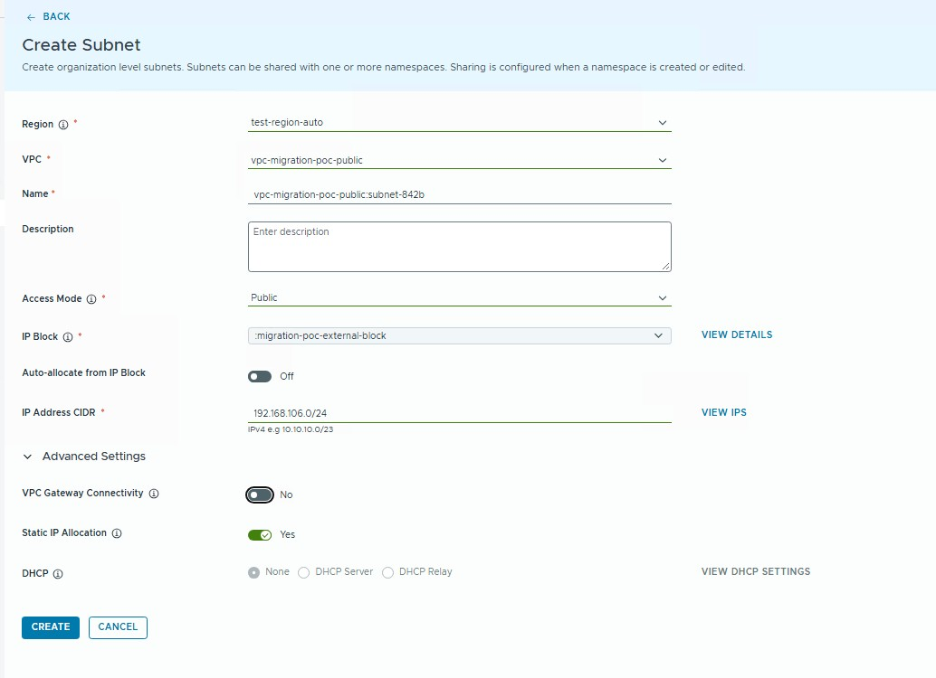
Figure 5. Public subnet with VPC Gateway Connectivity Off. The screenshot comes from an earlier 192.168.106.0/24 test; the settings are identical for 192.168.107.0/24.
Do not enable VPC Gateway Connectivity at this stage.
The source Tier-1 still owns
192.168.107.1. The target gateway is enabled only during the controlled L3 cutover in Part 6.
Step 8 – Create the Namespace and Share the Subnet
- Open Manage & Govern > Namespaces > NEW NAMESPACE.
- Select the project and the target VPC.
- Create the namespace in my lab
migration-poc-public-107-ns-2c7tm. - Edit the namespace and add
subnet-c5mk/192.168.107.0/24under Subnets. - Save and wait until the namespace becomes Active.
Now verify it from the Supervisor Control Plane:
kubectl get subnets.crd.nsx.vmware.com \
  -n migration-poc-public-107-ns-2c7tm
Expected result:
NAME          ACCESSMODE   NETWORKADDRESSES
subnet-c5mk   Public       192.168.107.0/24
Checkpoint: if you get No resources found, do not start the import. Mobility Operator would create a SubnetPort referencing a missing Subnet CR and stop at NetworkBackingReady=False.
Part 4 – Prepare the Source Network and Build the L2 Bridge
Step 9 – Prepare the Source Segment and the Test VM
In my lab I built the source side from scratch, so that I could test it end to end. In production, this is your existing segment.
- In NSX Manager, open Networking > Segments > Add Segment.
- Name:
vcf-migration-test-public. - Transport Zone:
overlay-tz-mgmt-nsxt. - Connected Gateway:
vworld-t1-gw01. - Subnet/Gateway:
192.168.107.1/24. - Attach the MAC Discovery profile
migration-mac-learning(Step 10). - Run
test-0006on the segment with IP192.168.107.20/24and gateway192.168.107.1. - From an external host, start a continuous ping to
192.168.107.20and keep it running for the whole migration.
Now verify the source route on Tier-0:
curl -sk -u "${NSX_USER}:${NSX_PASS}" \
  "${NSX}/policy/api/v1/infra/tier-0s/${T0_ID}/routing-table" \
  | jq '.results[]?.route_entries[]? | select(.network=="192.168.107.0/24")'
Checkpoint: before migration, expect route_type=t1c, admin_distance=3, next_hop=100.64.0.1.
Shared bridge infrastructure
Steps 10 to 14 are done once per environment, not once per VM. Future migrations reuse the Bridge Profile, VLAN Transport Zone, and parent segment; each new L2 domain only gets a new bridge VLAN.
Step 10 – Create the MAC Discovery Profile
Open Networking > Profiles > Segment Profiles > MAC Discovery > Add. My lab name was migration-mac-learning.
| Setting | Value | Why |
|---|---|---|
| MAC Change | Yes | Required when traffic crosses the bridge |
| MAC Learning | Yes | Learns the guest MAC behind the bridge |
| Unknown Unicast Flooding | No | Avoids unnecessary flooding |
| MAC Limit | 4096 | Lab value; size it for production |
Step 11 – Create a Dedicated VLAN Transport Zone and Edge Switch
My first idea was to reuse the existing VLAN TZ on a second Edge host switch. NSX refused it, because a Transport Zone must be unique across host switches. So I created a dedicated one.
- Open System > Fabric > Transport Zones > Add Transport Zone.
- Name:
migration-bridge-vlan-tz, Traffic Type: VLAN. Save. - Open System > Fabric > Nodes > Edge Transport Nodes and edit each Edge used by the bridge.
- Add an additional VLAN switch with uplink profile
nsx-edge-single-nic-uplink-profile. - Attach
migration-bridge-vlan-tzto the switch. - Uplink/interface:
fp-eth2. - Repeat for the primary and backup Edge.
Step 12 – Create the Parent Overlay Segment and Connect the Edge vNIC
- In NSX Manager, open Networking > Segments > Add Segment.
- Name:
migration-parent-seg, Transport Zone:overlay-tz-mgmt-nsxt, Gateway: None, Subnet: empty. - In the vSphere Client, edit the Edge VM and connect the extra adapter (in my lab, Network Adapter 4 /
fp-eth2) tomigration-parent-seg. - Repeat for both Edges.
Checkpoint: the parent segment shows two Edge ports.
Step 13 – Create the Edge Bridge Profile
- Open Networking > Segments > Edge Bridge Profiles.
- Create
migration-poc-bridge-profilewith Edge Clustervworld-edge-cl01, primary Edgevcf-edge-01and backup Edgevcf-edge-02. - Save.
Checkpoint: the profile is Success / Realized.
Step 14 – Share the Bridge Profile and VLAN TZ with the NSX Project
The BridgeConnection lives under the VPC project path, while the Bridge Profile and VLAN TZ are infra resources. They must be visible to the project. In my lab, I shared both into test-org-auto (a85bcc0c-ad2f-45bb-9593-b7640713f0dc) using NSX resource sharing:
/infra/sites/default/enforcement-points/default/edge-bridge-profiles/migration-poc-bridge-profile
/infra/sites/default/enforcement-points/default/transport-zones/migration-bridge-vlan-tz
Per-migration bridge
Now we build the bridge for this specific subnet. The VLAN is only an internal bridge mapping tag, but it must be unique for the L2 domain. I used VLAN 102.
export PROJECT_ID="a85bcc0c-ad2f-45bb-9593-b7640713f0dc"
export SOURCE_SEGMENT_ID="vcf-migration-test-public"
export VPC_ID="vpc-migration-poc-public-107"
export SUBNET_ID="subnet-c5mk"
export PARENT_SEGMENT_PATH="/infra/segments/migration-parent-seg"
export BRIDGE_PROFILE_PATH="/infra/sites/default/enforcement-points/default/edge-bridge-profiles/migration-poc-bridge-profile"
export VLAN_TZ_PATH="/infra/sites/default/enforcement-points/default/transport-zones/migration-bridge-vlan-tz"
export BRIDGE_VLAN="102"
export BINDING_ID="migration-bind-102"
Step 15 – Do Not Guess VPC_ID and SUBNET_ID
curl -sk -u "${NSX_USER}:${NSX_PASS}" \
  "${NSX}/policy/api/v1/orgs/default/projects/${PROJECT_ID}/vpcs" \
  | jq '.results[] | {id,display_name,path}'

curl -sk -u "${NSX_USER}:${NSX_PASS}" \
  "${NSX}/policy/api/v1/orgs/default/projects/${PROJECT_ID}/vpcs/${VPC_ID}/subnets" \
  | jq '.results[] | {id,display_name,access_mode,ip_addresses,connectivity_state}'
Watch out for look-alike VPCs.
In my lab there was also a namespace-generated VPC with a similar name, containing only an
_servicessubnet. The BridgeConnection must point to the VPC that actually holds the Public subnet.
Step 16 – Create the Target BridgeConnection
curl -sk -u "${NSX_USER}:${NSX_PASS}" -X PUT \
  "${NSX}/policy/api/v1/orgs/default/projects/${PROJECT_ID}/vpcs/${VPC_ID}/subnets/${SUBNET_ID}/bridge-connections/migration-bridge-102" \
  -H 'Content-Type: application/json' \
  -d "{
    \"display_name\": \"migration-bridge-102\",
    \"bridge_profile_path\": \"${BRIDGE_PROFILE_PATH}\",
    \"vlan_ids\": [\"${BRIDGE_VLAN}\"],
    \"vlan_transport_zone_path\": \"${VLAN_TZ_PATH}\"
  }" | jq .
The property name must be vlan_transport_zone_path. With transport_zone_path the API returns BAD_REQUEST: property unrecognized.
Step 17 – Create the Source SegmentConnectionBindingMap
curl -sk -u "${NSX_USER}:${NSX_PASS}" -X PUT \
  "${NSX}/policy/api/v1/infra/segments/${SOURCE_SEGMENT_ID}/segment-connection-binding-maps/${BINDING_ID}" \
  -H 'Content-Type: application/json' \
  -d "{
    \"display_name\": \"${BINDING_ID}\",
    \"segment_path\": \"${PARENT_SEGMENT_PATH}\",
    \"vlan_traffic_tag\": ${BRIDGE_VLAN}
  }" | jq .
Step 18 – Verify the Realized State
curl -sk -u "${NSX_USER}:${NSX_PASS}" \
  "${NSX}/policy/api/v1/infra/realized-state/realized-entities?intent_path=/orgs/default/projects/${PROJECT_ID}/vpcs/${VPC_ID}/subnets/${SUBNET_ID}/bridge-connections/migration-bridge-102" \
  | jq .
Checkpoint: expect at least RealizedLogicalPort and RealizedBridgeEndpoint with state=REALIZED. The SegmentConnectionBindingMap may not expose its own realized-state record; a successful PUT and a working dataplane are what matter.
Part 5 – Import the Running VM with Mobility Operator
Step 19 – Find the VM MoRef and the NIC Device Key
export VC="https://vcf-vcsa.vcf.vworld.lab"
export VC_USER="administrator@vsphere.local"
export VC_PASS="<PASSWORD>"
export VC_SESSION=$(curl -sk -u "${VC_USER}:${VC_PASS}" -X POST "${VC}/api/session" | tr -d '"')

curl -sk -H "vmware-api-session-id: ${VC_SESSION}" "${VC}/api/vcenter/vm" \
  | jq '.[] | select(.name=="test-0006")'
The filter.names query parameter was not supported in my lab, so I listed all VMs and filtered locally with jq. The result was vm-4039. Now the NIC:
export VM_MOID="vm-4039"

curl -sk -H "vmware-api-session-id: ${VC_SESSION}" \
  "${VC}/api/vcenter/vm/${VM_MOID}/hardware/ethernet" | jq .
The NIC device key was 4000.
Step 20 – Create the ImportOperationBatch in Precheck Mode
We start with a dry run. precheckOnly: true validates everything without touching the VM, and commitAction: Wait makes sure nothing is committed automatically.
apiVersion: mobility-operator.vmware.com/v1alpha3
kind: ImportOperationBatch
metadata:
  name: import-test-0006
  namespace: migration-poc-public-107-ns-2c7tm
spec:
  defaultSpec:
    mode: preserve
    controlAction:
      precheckOnly: true
      commitAction: Wait
  operations:
    - name: test-0006
      spec:
        virtualMachineID: vm-4039
        networkInterfaces:
          - deviceKey: 4000
            subnetInfo:
              apiGroup: crd.nsx.vmware.com
              kind: Subnet
              name: subnet-c5mk
kubectl apply -f import-test-0006.yaml
kubectl get importoperationbatch import-test-0006 \
-n migration-poc-public-107-ns-2c7tm -o yaml
kubectl get importoperation test-0006 \
-n migration-poc-public-107-ns-2c7tm -o yamlCheckpoint: the precheck must show PrecheckSucceeded=True and the preserved addressing: 192.168.107.20/24, gateway 192.168.107.1 and MAC 00:50:56:9c:6e:cc.
Step 21 – Execute the Import Without Committing
- Make sure the continuous ping to
192.168.107.20is still running. - Edit the batch:
kubectl edit importoperationbatch import-test-0006 \
-n migration-poc-public-107-ns-2c7tm- Change only
precheckOnly: truetofalse. KeepcommitAction: Waitandmode: preserve. - Save and watch the operation:
kubectl get importoperation test-0006 \
  -n migration-poc-public-107-ns-2c7tm -w
Wait for all of these conditions:
NetworkBackingReady=True
ReadyForCommit=True
VirtualMachineCreated=True
VirtualMachineReady=True
VirtualMachineReadyForImport=True
VirtualMachineSetManagedBySucceeded=True
The key evidence
stateTransitionsshould still showsource.powerState=poweredOn. This is the proof that the import happens without a planned power-off.
At this point, the VM NIC is already on the target SubnetPort, but its traffic still goes over the bridge to the source Tier-1.
Step 22 – Commit the Import
- Inside the guest, verify ping,
uptime,ip addrandip route. - Edit the batch again and change
commitAction: WaittoAuto. KeepprecheckOnly: falseandmode: preserve. - Watch the ImportOperation until
Completed=True.
After commit, the VM is represented as a vmoperator.vmware.com/v1alpha5 VirtualMachine in the namespace. Routing, however, still returns to the source Tier-1 over the bridge. That is what we change next.
Part 6 – The L3 Cutover
This is the moment where the target VPC takes over routing for the prefix. Keep the ping window visible.
Step 23 – Confirm the Source t1c Route
curl -sk -u "${NSX_USER}:${NSX_PASS}" \
  "${NSX}/policy/api/v1/infra/tier-0s/${T0_ID}/routing-table" \
  | jq '.results[]?.route_entries[]? | select(.network=="192.168.107.0/24")'
Checkpoint: route_type=t1c, next_hop=100.64.0.1.
Step 24 – Deny Source Advertisement for the Migrated Prefix Only
- In NSX Manager, open Networking > Tier-1 Gateways > vworld-t1-gw01 > Edit.
- Open Route Advertisement > Set Route Advertisement Rules.
- Add a rule:
| Field | Value |
|---|---|
| Name | migration-107-cutover-deny |
| Network | 192.168.107.0/24 |
| Prefix Operator | EQ |
| Action | Deny |
| Route Type | Connected Segments & Service Ports |
- Save.
Do not disable connected routes globally.
The source Tier-1 may serve many other networks. The deny rule must hit only the migrated prefix.
After saving, t1c disappears from Tier-0, and the external ping may stop for a moment.
Step 25 – Enable VPC Gateway Connectivity on the Target Subnet
- In VCF Automation, open Manage & Govern > Subnets.
- Open the target Public subnet
192.168.107.0/24. - Edit and switch VPC Gateway Connectivity to On.
- Save and wait a few seconds.
- Check the Tier-0 routing table again.
The prefix should now appear as:
route_type: tgws
network: 192.168.107.0/24
admin_distance: 5
next_hop: 169.254.64.15
black_hole: false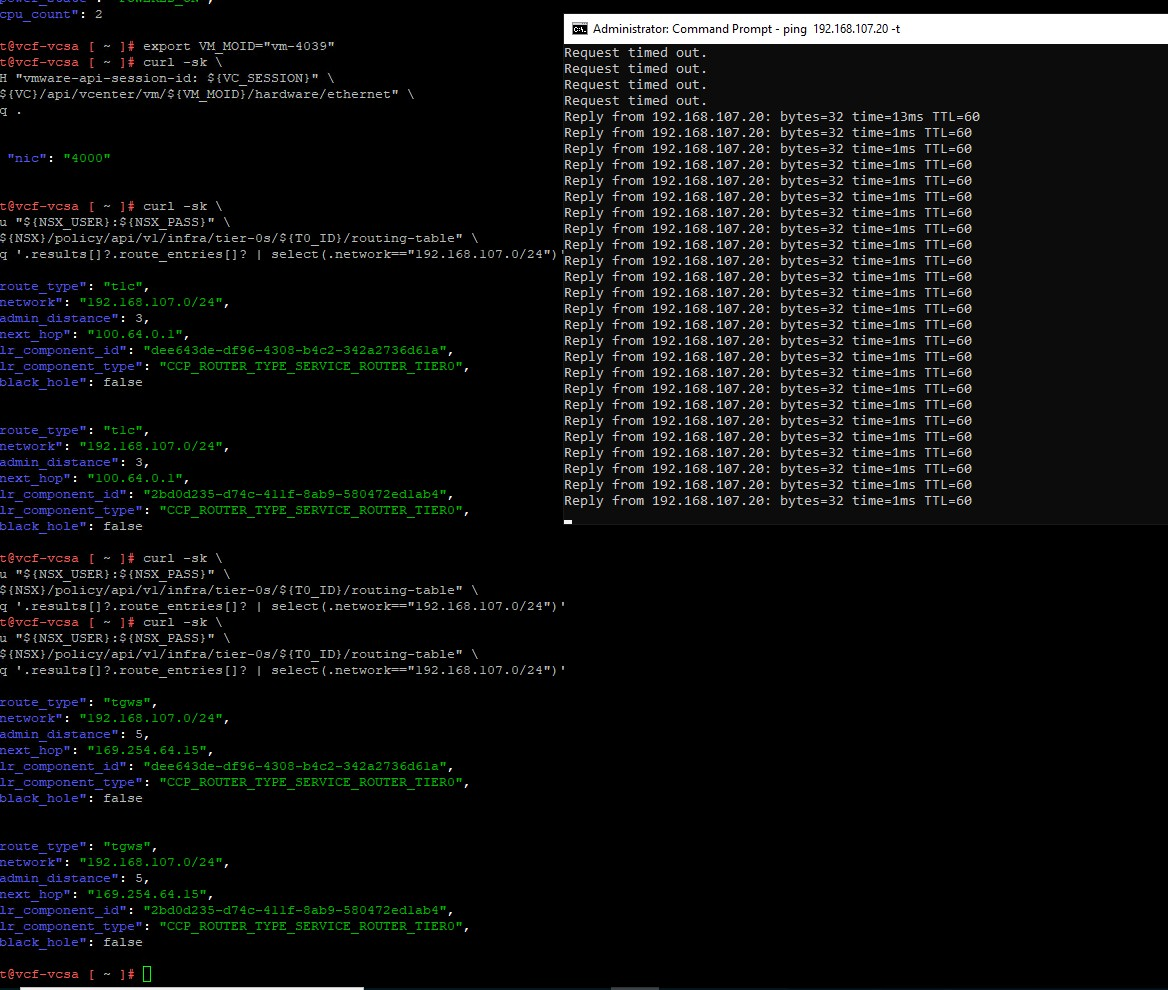
Figure 6. The final cutover: t1c first, a short ping interruption, then tgws via 169.254.64.15 and a stable ping to 192.168.107.20.
In my lab, the ping showed only a few Request timed out lines before replies came back through the TGW. Keep the bridge active for now; it is your safety net.
Part 7 – Validate and Remove the Bridge
Step 26 – Post-Cutover Validation
- External ping to the VM is stable.
- Tier-0 shows only
tgwsfor the migrated/24, nott1c. - The VM still has
192.168.107.20/24. - The guest default gateway is still
192.168.107.1. - The MAC is still
00:50:56:9c:6e:cc. uptimewas not reset.- ImportOperation reports
Completed=True. - vSphere shows Managed By / WCP Service, and the VM is in the target resource pool and network backing.
- The application on the VM responds, not only ICMP.
Step 27 – Remove the Per-Network Bridge Objects
Once target routing is proven independent, remove the objects created for this subnet. The shared bridge infrastructure can stay for future migrations.
curl -sk -u "${NSX_USER}:${NSX_PASS}" -X DELETE \
  "${NSX}/policy/api/v1/infra/segments/${SOURCE_SEGMENT_ID}/segment-connection-binding-maps/${BINDING_ID}"

curl -sk -u "${NSX_USER}:${NSX_PASS}" -X DELETE \
  "${NSX}/policy/api/v1/orgs/default/projects/${PROJECT_ID}/vpcs/${VPC_ID}/subnets/${SUBNET_ID}/bridge-connections/migration-bridge-102"
Checkpoint: after bridge removal, ping and the application must keep working. This is the final proof that the VM uses only the target dataplane.
L3 Rollback Before Bridge Removal
If traffic does not recover after enabling Gateway Connectivity, do not reverse the VM import. As long as the bridge exists, L3 can simply go back to the source:
- Disable VPC Gateway Connectivity on the target Public subnet.
- Confirm that
tgwsfor192.168.107.0/24disappears from Tier-0. - Remove
migration-107-cutover-denyfromvworld-t1-gw01. - Confirm that
t1creturns via100.64.0.1. - Ping recovers via target NIC -> L2 bridge -> source segment -> source Tier-1.
- Troubleshoot, then repeat the cutover.
Conclusion
We started with a running VM on a classic NSX segment behind an old Tier-1. We ended with the same VM, with the same IP, MAC, gateway, and uptime, managed by vSphere Supervisor and VM Service, and routed through a VPC, a Transit Gateway, and a Centralized External Connection.
Three elements make it work: a correctly built L2 bridge, Mobility Operator in mode: preserve, and a target Public subnet backed by an External IP Block that the existing External Connection can advertise. Everything else is about doing things in the right order.
The most interesting part, at least for me, is the moment on Tier-0 when route_type=t1c disappears and route_type=tgws shows up. That single line in the routing table is where the old world hands over to the new one.
From an infrastructure perspective, this is a precise, multi-layer change touching the provider, the tenant, the Edge, and Kubernetes.
From the application perspective, it is a few missed pings.
In production, treat every migration like this as a controlled network and application change: establish prefix ownership, monitor both dataplanes, keep the bridge until validation is complete, and always have the L3 rollback ready.